

Selecting a smart camera is one part of building a reliable 2D inspection system. The lens determines what the camera can see at a given working distance. Lighting brings the features of interest into view. Filters, cabling, power, and mounting hardware complete the installation.
The Gocator® 2D 1050 and 1120 Smart Cameras support a range of accessories for configuring these elements around the inspection task. The accessory diagrams included show the available paths for each camera, from optics and illumination to network and power connections.
Start with the Image You Need
Define the required field of view, working distance, smallest feature of interest, and surface characteristics before choosing a lens or light. A wider view can cover more of a part, while a narrower view can provide more image detail over a smaller area. Reflective surfaces, changing ambient light, and moving parts may require a different illumination approach than a stationary, matte target.
The accessory configuration should also account for the installation: cable runs, available power, camera mounting, and the level of protection required around the lens.
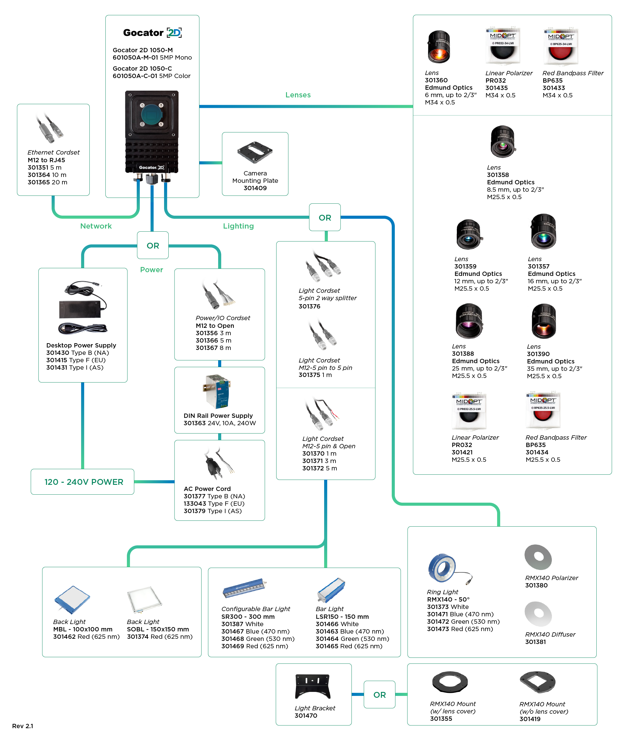
Choose Optics for the Gocator 2D 1050
The 5 MP Gocator 2D 1050 is available in monochrome and color models. Its accessory selection includes Edmund Optics lenses with focal lengths of 6, 8.5, 12, 16, 25, and 35 mm. These options support different combinations of field of view and working distance for tasks such as presence checks, code reading, measurement, and defect inspection.
Linear polarizers and red bandpass filters are available in thread sizes matched to the applicable lens configurations. The 6 mm lens uses an M34 × 0.5 filter thread; the listed 8.5–35 mm lenses use M25.5 × 0.5. Check the accessory diagram when specifying a filter so its thread matches the selected lens.
Choose Optics for the Gocator 2D 1120
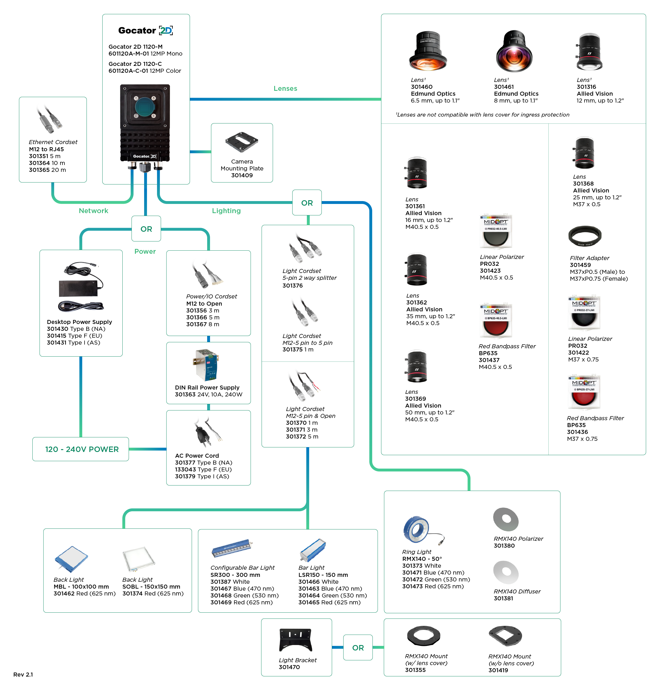
The 12 MP Gocator 2D 1120 is also available in monochrome and color models. Its listed lens options span 6.5 to 50 mm, with selections from Edmund Optics and Allied Vision. The range gives system designers options for larger fields of view or finer detail at the required working distance.
Filter compatibility depends on the lens. The accessory diagram identifies M40.5 × 0.5 and M37 × 0.75 polarizer and red bandpass filter options, as well as a filter adapter for the applicable 25 mm lens configuration. Specify the lens, filter, and adapter as a matched set.
Ingress protection requires particular attention: the Rev 2.1 guide marks the 1120’s 6.5 mm, 8 mm, and 12 mm lenses as incompatible with the lens cover for ingress protection. Confirm the complete optical configuration against the installation’s protection requirements before selecting one of these lenses.
Shape Contrast with the Right Light
Good illumination makes the inspection feature distinguishable from its surroundings. The Gocator 2D accessory range includes ring lights, bar lights, and backlights, each suited to a different way of presenting the part to the camera.
Ring Lights
The RMX140 ring light illuminates around the camera’s viewing axis. It is available in white, blue, green, and red. An optional polarizer or diffuser can help manage reflections or soften illumination, depending on the target. Mounting options are listed with and without a lens cover.
Bar Lights
Bar lights provide directional illumination that can bring out edges, texture, or surface features. The accessory diagrams list a 150 mm LSR150 bar light and a 300 mm SR300 configurable bar light, each with white, blue, green, and red options. Their placement and angle should be tested against the actual part to produce the required contrast.
Backlights
A backlight places the part between the light and camera to create a silhouette. This is useful when the inspection depends on an outline, edge position, presence check, or dimensional measurement. The diagrams list red MBL 100 × 100 mm and SOBL 150 × 150 mm backlight options.
Light color, geometry, and exposure should be evaluated together. The best choice depends on the material, the feature being inspected, and the production environment.
Complete the Installation
Both camera diagrams show the supporting components needed to connect and mount the system:
- Networking: M12-to-RJ45 Ethernet cordsets in 5, 10, and 20 m lengths.
- Power and I/O: M12-to-open cordsets in 3, 5, and 8 m lengths.
- Lighting connections: light cordsets and a five-pin, two-way splitter for applicable lighting configurations.
- Power supplies: regional desktop power-supply options or a 24 V, 10 A DIN rail power supply, with regional AC power cords listed for the DIN rail configuration.
- Mounting: a camera mounting plate, light bracket, and ring-light mount options.
Choose cable lengths and power hardware based on the physical layout of the station. Use the appropriate diagram to verify the connections and accessory part numbers for the selected camera and lighting arrangement.
Configure Around the Application
A successful accessory selection begins with an image of the real part under representative production conditions. Establish the field of view and detail required, select a compatible lens, then test lighting and filters to make the inspection feature repeatable. Finally, confirm mounting, cable routing, power, and any lens-cover requirements.
The Gocator 2D 1050 and 1120 accessory diagrams provide a practical reference for that process. Review the configuration for your camera or contact LMI Technologies to discuss the optical and installation requirements of your inspection.