This week’s blog post is contributed by 3D3 Solutions’ UK distributor, Simon Stone from Mech Innovation Limited.
What is Reverse Engineering?
Reverse engineering refers to the process of analyzing the construction of a product when there are no design documents available from its original production. Reverse engineering serves many purposes including:
- developing a similar or improved product/design
- creating adaptors or enclosures to the original product
- reproducing an existing part
The process involves taking measurements of the object with the use of a 3D scanner and then using the 3D data to create a 3D CAD (computer-aided drawing) model. A CAD model is the standard format for manufacturing.
Does 3D scanning an object produce a CAD Model?
A common misunderstanding of the 3D scanning process is that the direct output is a CAD model that can imported into any CAD system. Unfortunately, this is not the case. The direct output of all optical scanners is point cloud or polygon mesh data. A CAD modelling stage is needed if a geometric solid model is required.
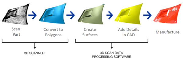
PHOTO SOURCE: Geomagic
If you have the right software and experience, point cloud data tells you everything you need to know in order to reconstruct a part in CAD. Unfortunately most mainstream CAD packages (example: AutoCAD, Rhino3D, Solidworks) are not particularly good at working with this type of data. 3D scan data processing software (example: Geomagic, Rapidform XOR and Polyworks) are great at converting point cloud data into CAD models.
Why use 3D scanning for this process?
It is difficult to take measurements of objects with organic or complex shapes. It is easy and fast to achieve this task using a 3D scanner since we can get measurements of an object from 3D scans rather quickly. A Coordinate Measuring Machine (CMM) only provides a discrete number of points, and although very accurate, it doesn’t compare to the information acquired by scanning, which shows how the surfaces flow.
What do you model when reverse engineering?
When 3D scanning an object, all surface geometry is captured, including imperfections caused by the manufacturing process and any damage the part may have suffered. Typically the part will be remodelled to capture the design intent and to disregard imperfections. There are some good reasons for this. Firstly, modelling in every single defect could be time consuming and therefore expensive. Secondly, one of the main reasons for reverse engineering is to remake the part. Therefore the requirement is to create a ‘perfect’ part representing true design intent. This may require a detailed understanding of the function (depending on the part being modelled) because only then can the design intent be correctly interpreted.
Do you have any questions related to reverse engineering? Please post in the comments section.